Comprehensive Overview of Automatic Power Factor Regulators #
 Automatic Power Factor Regulator - Yuhchang
Introduction #
Automatic Power Factor Regulators (APFRs) are essential devices for maintaining optimal power factor in electrical systems. By continuously monitoring and adjusting the power factor, these regulators help improve energy efficiency, reduce losses, and ensure the reliable operation of electrical equipment.
Key Features #
- Auto/Manual Operating Modes: Flexible operation allows users to select between automatic and manual control, adapting to various application needs.
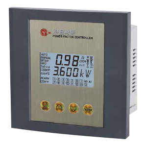
- Comprehensive Parameter Measurement: Measures a wide range of electrical parameters, including current (A), voltage (V), apparent power (VA), active power (Watt), reactive power (Var), power factor (PF), frequency (Hz), temperature (°C), total harmonic distortion of voltage (THD-V), and current (THD-I).
- Clear LCD Display: All measured parameters are directly readable on an LCD screen, with clear symbols for easy identification.
- Independent Alarm for Cooling: An independent alarm can activate a fan to cool the area around the inner cabinet, ensuring safe operation.
- Bargraph Indication: Visual bargraph indicators for current, voltage, and temperature provide at-a-glance system status.
- Versatile Switching Modes: Multiple switching configurations enable users to optimize the power factor target according to system requirements.
- Auto-Reversal Correction: Automatically corrects for incorrect phase sequence, enhancing installation flexibility and safety.
- Parameter Memory: Memorizes initial and actual operating parameters for switched-on capacitors, supporting system diagnostics and maintenance.
- Operating Time and Event Recording: Tracks the running hours and the number of switching events for each capacitor, aiding in maintenance planning.
- Abnormal Status Indication: Alerts users to abnormal operating conditions for prompt intervention.
- Built-in Temperature Sensor: Monitors internal temperature to protect components and ensure reliable operation.
- THD-Based Switching Control: Allows setup of THD-I/THD-V thresholds (in %) for switching off capacitors, protecting against excessive harmonics.
- Alarm Setup for Current/Voltage: Configurable alarms for under/over-current and voltage (in %) enhance system protection.
- Adjustable Delay Time: Users can set delay times for switching capacitors on or off, reducing wear and optimizing performance.
Model Specifications #
| Model | Steps | Operating Voltage | Operating Temperature | Dimension (mm) | Panel Cut-Out (mm) |
|---|---|---|---|---|---|
| YPD-6 | 3~6 steps (programmable) | AC 220/380V | 0 ~ 60℃ | 144 x 144 x 62 | 138 x 138 |
| YPD-12 | 3~12 steps (programmable) | AC 220/380V | 0 ~ 60℃ | 144 x 144 x 62 | 138 x 138 |
| YPM-7 | 3~7 steps (programmable) | AC 90/550V | 0 ~ 60℃ | 144 x 144 x 62 | 138 x 138 |
| YPM-14 | 3~14 steps (programmable) | AC 90/550V | 0 ~ 60℃ | 144 x 144 x 62 | 138 x 138 |
For more detailed information, refer to the Catalog Download or Contact Us.